Custom Finger Brake Bending Die
Designed to be used with SWAG 20 TON Finger Brake DIY Builder Kit
Introduction
I needed a quick and relatively cheap way of bending 1/2” x 2” 6061-T6 aluminum bar stock to manufacture a custom strut tower brace for a BMW Z3. Outsourcing the bending to another shop would have eaten away at all my profits, so that wasn’t an option. My immediate resources where a SWAG Off Road 20 Ton Finger Brake Kit and a hydraulic press capable of providing enough pressure to bend the bar stock for the brace. The only missing piece to the equation was the proper bending die, and the only bending dies available were those that came with the press. Unfortunately, their bend radii where all much too small to properly bend the 1/2” material without causing serious deformation. Alternative solutions would be a custom made die from a tool manufacture or an off the shelf tool. Both options where way out of budget at the time so what remained was designing and making my own.
It was time to put my design skills to the work. Researching bending science, I learned of a general rule for bending. This rule states that, at minimum, the radius of the bend die must be equal to the thickness of the material being bent. With that in mind, I went ahead and designed an upper and lower die to be made out of 1/2” steel plate that I could have SendCutSend cut for me. Initially I wanted to use 4140 chromoly steel for the upper and lower portions of my die due to its high yield strength but, that material was unavailable to me. So a quick calculation with some worst case surface area contact assumptions allowed me to estimate the pressures my bending die components would be experiencing which to my benefit was well below the yield strength of A36 (low carbon cheaper steel) and available to me. So I had the plates cut from A36 steel and prepared for the build.
Design

The Lower die was designed to have a 2” bend radius on the bending surface areas where the aluminum bar stock rolls over during the bending process. The trough of the die was designed with extra relief so the bar stock could be bent further than designed just in case I needed to account for any spring back effects. Bevels where cut into the plates to maximize weld penetration between plates and make for a sturdy bound. The idea behind this design was to slap 4+ of these plates back to back and weld them together to make a surface large enough for the bar stock to sit on during bending.

In the Image to the right, one can see the stack of upper and lower plates with bevels aligned. The upper bend die also has the hardened steel shaft attached to the stack of plate steel on the curved surface. All plates are MIG welded together and the steel shaft is centered about the upper plates and TIG welded to them for aesthetics but it could have been MIG welded as well.

The upper die was designed to have an arc with a radius of 1/2” to accommodate a piece of 1” hardened steel shaft. This shaft would then be TIG welded to the Upper Bending Die and used as the contact surface for bending the bar stock. Similar to the Lower Bending Die 4 or more of these plates were to be placed back to back and then welded together along the beveled surfaces.

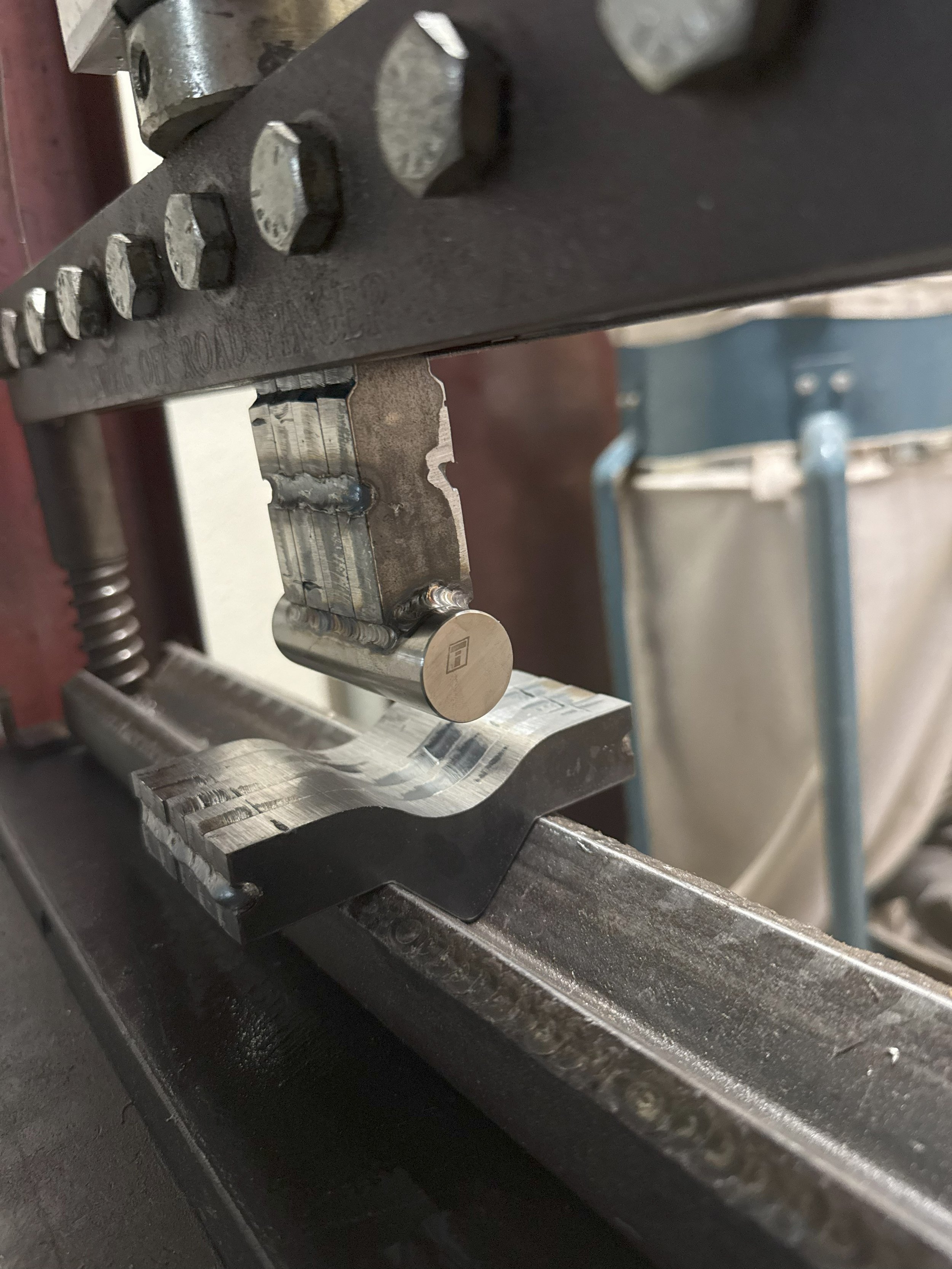
The assembly can be seen on the image to the right. The Lower die assembly was designed to to sit within the bed of the SWAG 20 TON Finger Brake DIY Builder Kit and the Upper die clamped withing the ram. And that’s it not much else to it, very straight forward.
Some future modification that I would like to add to this die are a stock alignment mechanism that keeps the stock perpendicular to the bend axis. I would also like to design a way to add a stop so that I always bend at the same length from the end of the material.
Build
Watch the video below to see the steps taken to build up the custom finger brake bending die.
Test
Watch the following video to see the bending die bend a piece of 1/2” x 2” piece of 6061-T6 aluminum bar stock.
Results
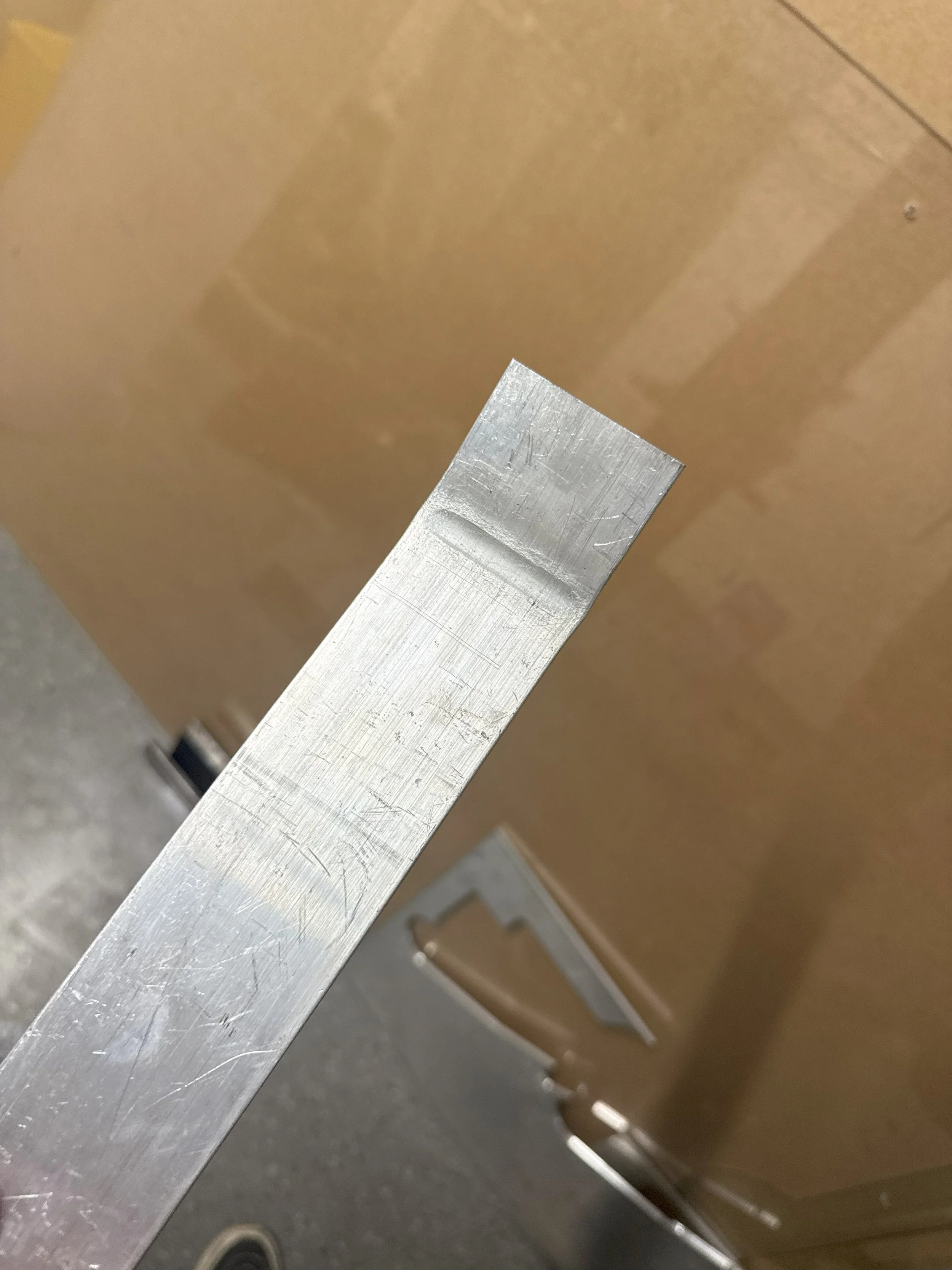
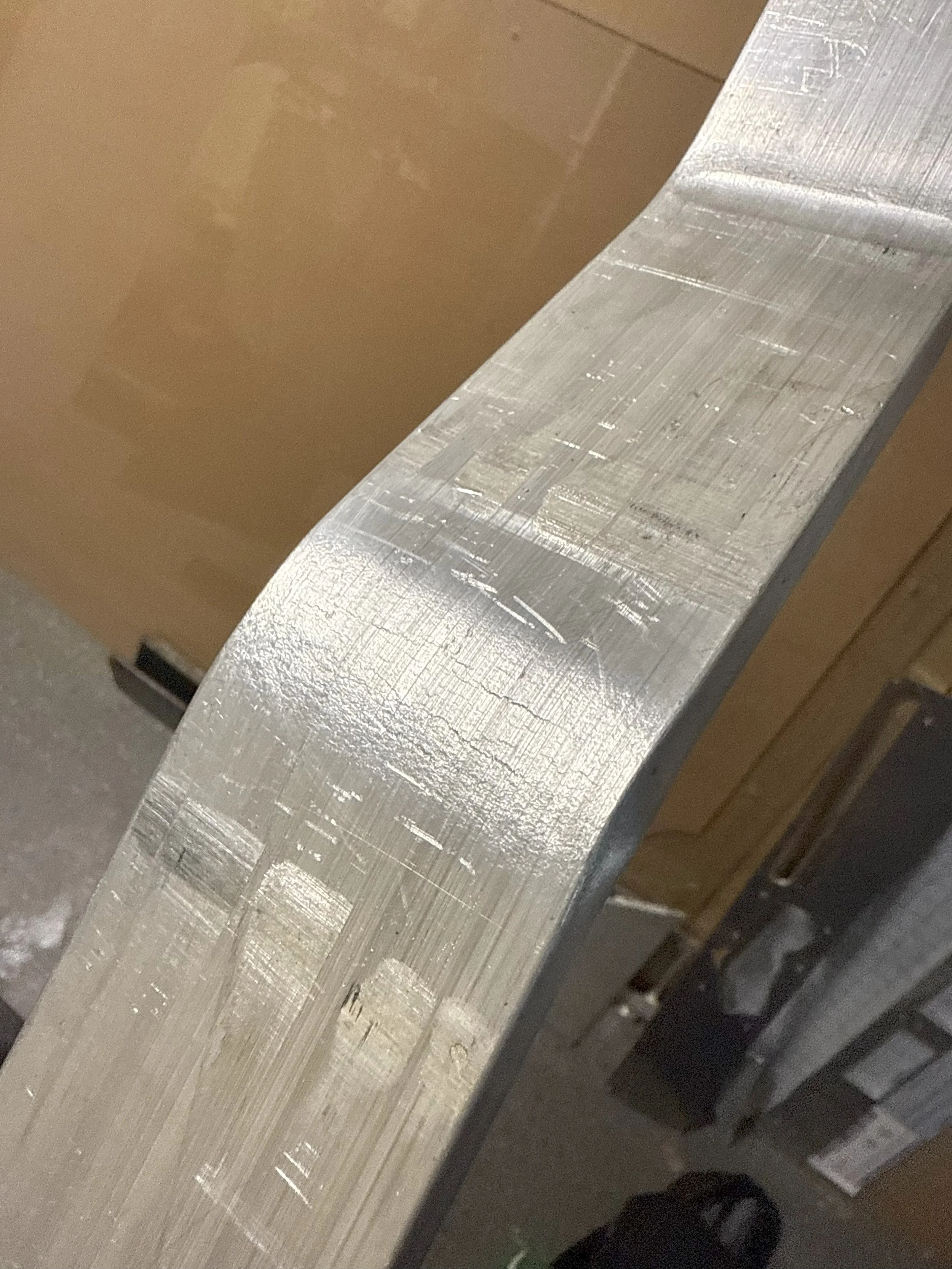
Below are images of the bent 1/2” x 2” 6061-T6 aluminum bar stock after being bent. From the first two images you can see the imprint left behind from the piece of 1” hardened steel shaft on the inner bend surface. If this where an issue we could use a larger diameter steel shaft to further distribute the bending force and leave less of a mark. On the outer side of the bend we can see that the material began to crack which is not desirable if the part is to go into an application requiring the full strength of 6061-T6 aluminum as those cracks could further develop under cyclical loading and eventually lead to failure. However, if the application does not require the full strength of T6 aluminum then this method will bend this particular bar stock while not deforming the material excessively.